
Apple II ROM Dumper
原文地址:http://quinndunki.com/blondihacks/?p=2409
A side quest to explore old code.
Something I’ve been wanting to do ever since acquiring my Apple IIc Plus at KansasFest is to dig into the ROM. Before the days of commodity Intel hardware, computers were very different things. Modern computers have this vestigial ROM-like thing called a BIOS, which is a minimal bit of goo used to get the mass storage device going when you turn the machine on. RAM is cheap, and the drives are fast, so it makes perfect sense to load as much of the operating system as possible into volatile memory. This gives you maximum flexibility- the software can be updated at any time, and the same set of hardware can run any combination of software and operating system.
In the 1970s and ’80s, however, the value propositions were all very different. Mass storage was only in the form of tapes (glacially slow) or floppy disks (merely very slow). RAM, meanwhile, was monumentally expensive. It’s hard to overstate the impact that the cost of RAM had on all electronics for a couple of generations. Nowadays, companies largely hold back RAM as a value-add to get you to spend more money. In the old days, however, the cost of RAM was the driving factor in nearly every architectural decision an engineer made in a computing system.
What is a 1980s computer designer to do? RAM costs a fortune, you need to hit a consumer-friendly price point, and you need an experience that doesn’t suck while trying to load an operating system from a 5¼” floppy disk or (gasp) cassette tape. The solution, as you probably know, was ROM. Mask ROMs, while expensive to develop, are relatively cheap to make in quantity. They are also basically (pardon the pun) as fast as RAM. As a result of these economic maths, computers of the period put significant portions of what we would now call “software” into ROM. Disk operating systems, programming languages, graphics libraries, windowing systems, hardware drivers, the list goes on. There’s almost no limit to what early computer designers would try to jam into ROM. It’s all in the name of saving precious RAM, and alleviating the need to load this stuff from slow mass storage every time you power on. It’s also worth noting that these early home computers were rebooted a lot. Vastly more than even the most unstable Windows machine. You generally rebooted every time you switched applications, and that was just the intentional reboots. If you were a developer, you might reboot as often as every couple of minutes (especially if developing interrupt code, or other sensitive low-level things). What we would now call a “blue screen of death” wasn’t just a subset of bugs that could occur. Virtually anything that went wrong in software brought the whole machine down. The point is, boot times mattered a lot. To that end, ROM was a huge win here. Later machines of this early generation, such as the Amiga, Apple IIgs, and original Mac, took this to extremes with positively huge ROMs. They were hundreds of kilobytes, and sometimes over a megabyte, of code. GUI systems, rendering libraries, font engines- all kinds of stuff was hiding in the silicon on the motherboard.
You can see the fruits of these efforts by simply turning on an old machine. It boots virtually instantly into a prompt that lets you write code, examine memory, debug, talk to peripherals, and all sorts of other things.
What’s the point of this history lesson? Well, despite edumicating the whipper snappers in the audience, the point is that there’s a lot of interesting old code locked up in the ROMs of these machines. I want to poke around in it. Who wouldn’t? It also helps to understand the obvious downside of this ROM-heavy approach to computing system design. This code can’t change. It’s set at manufacture time, and users have to live with it, bugs and all, for years or even decades. This became such a problem that some machines would patch the ROM by loading corrected code into RAM at startup, and directing applications to use that code instead. This, of course, defeats the whole purpose of the ROM while also slowing down boot times. The Amiga and Apple IIgs were particularly notorious for this. The other solution is to release new ROM revisions (something the IIgs also did a lot of), but this is slow and drives customers (and developers) crazy.
I realize that was a lot of words, and nobody likes reading. So let’s get to the point of this hack. I want to dig into the ROM of my Apple IIc Plus. The complete ROM contents of pretty much every Apple II model can be found online without much effort. In fact, the early machines came with complete ROM listings in their instruction manuals. Furthermore, early Apple II machines have a built in ROM Monitor that allows you to view and disassemble the contents of ROM. There are many convenient, easy ways to examine and explore this old ROM code.
I’m going to do none of that.
I want to do it the hard way, and dump the contents of the chip itself. Why? Because it’s fun, and also because the IIc Plus ROM is a bit more obscure and less well documented than most other Apple II models. This machine came at the very end of the run, didn’t sell well, and doesn’t get a lot of attention from hackers.
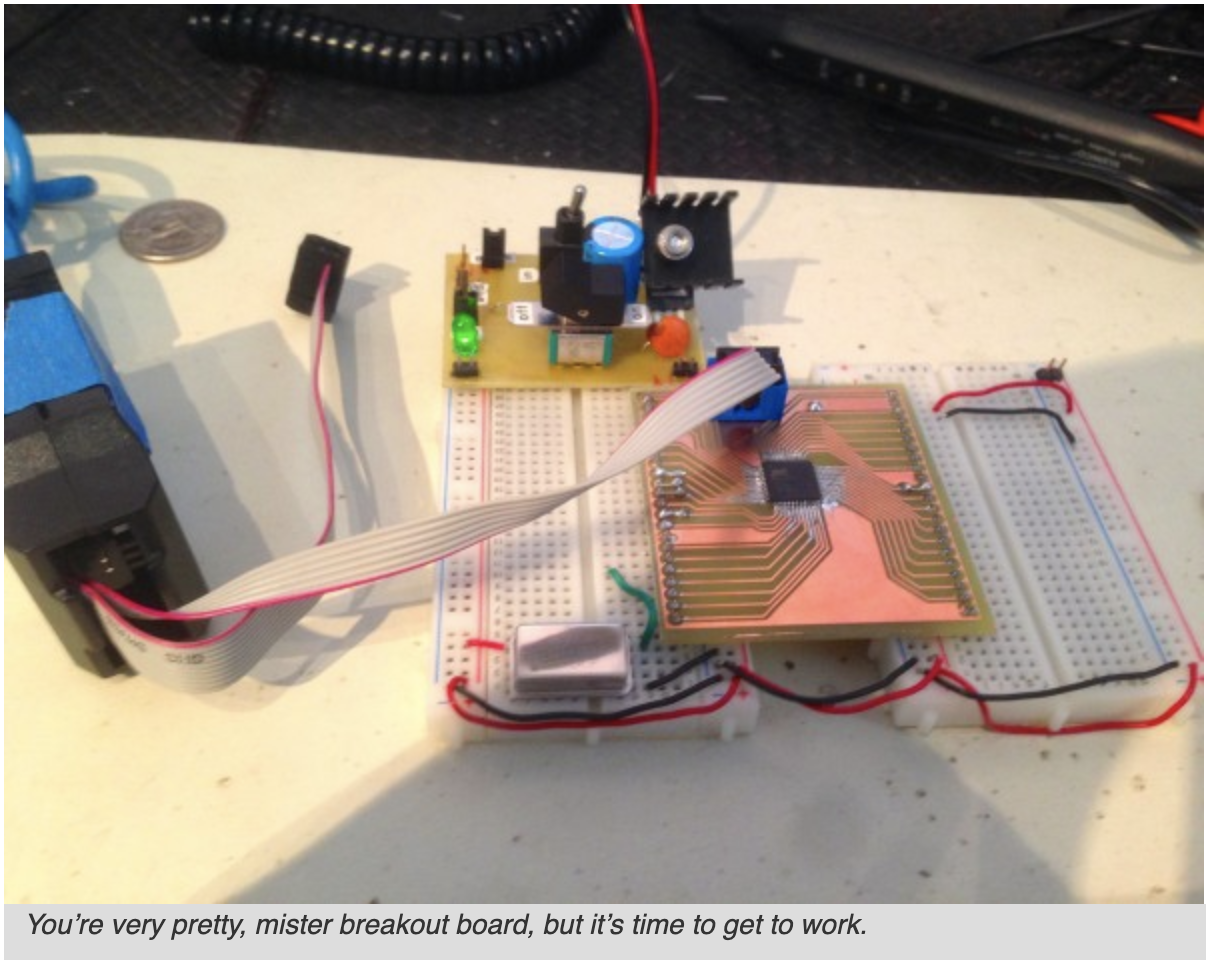
In a recent post, I put together a breakout board for the ATMega32U4. As you might have guessed, I had an ulterior motive for doing this. I intend to expand that into a dumper for Apple II ROM chips. It will also be expanded to an EEPROM writer, so I can modify the code. A ROM tool of this sort is nothing new on Blondihacks. I did this with an ATTiny microcontroller way back in the early days of Veronica. The old girl has an onboard EEPROM writer which is very useful for developing ROM code in-situ. However, that thing is very specialized to Veronica’s needs, and in fact was a giant pain in the ass to make. The ATTiny, while a favorite chip of mine, has very little general purpose IO. That means I needed to use a lot of shift registers to access all the address and data lines of an EEPROM, and that in turn made the code a hassle to get right. I also have somewhat grander visions for this new ROM tool. While Veronica’s EEPROM writer can only burn code that is held by the ATTiny itself (uploaded via AVR programmer), I wanted this new tool to stream the code over USB.
The basic design is to have a zero-insertion-force (ZIF) socket for the ROM chip, a USB port to connect to a computer, and a microcontroller to manage everything in between. I wanted a simple, low-chip-count design that would be easy for people to use (or potentially buy from me, if anyone wants one).
In an effort to simplify this task, I wanted a single chip that had enough I/O to wrangle a 32kbit EEPROM all by itself, and could speak USB. This led me to the ATMega32U4, and subsequent breakout board.
The software for this project is going to be relatively complex, but the hardware is quite simple. As I’ve mentioned previously, I’ve recently become quite enamored with KiCad. It will be pressed into service once again for this project. All the hardware and software files involved with the project are available on GitHub.
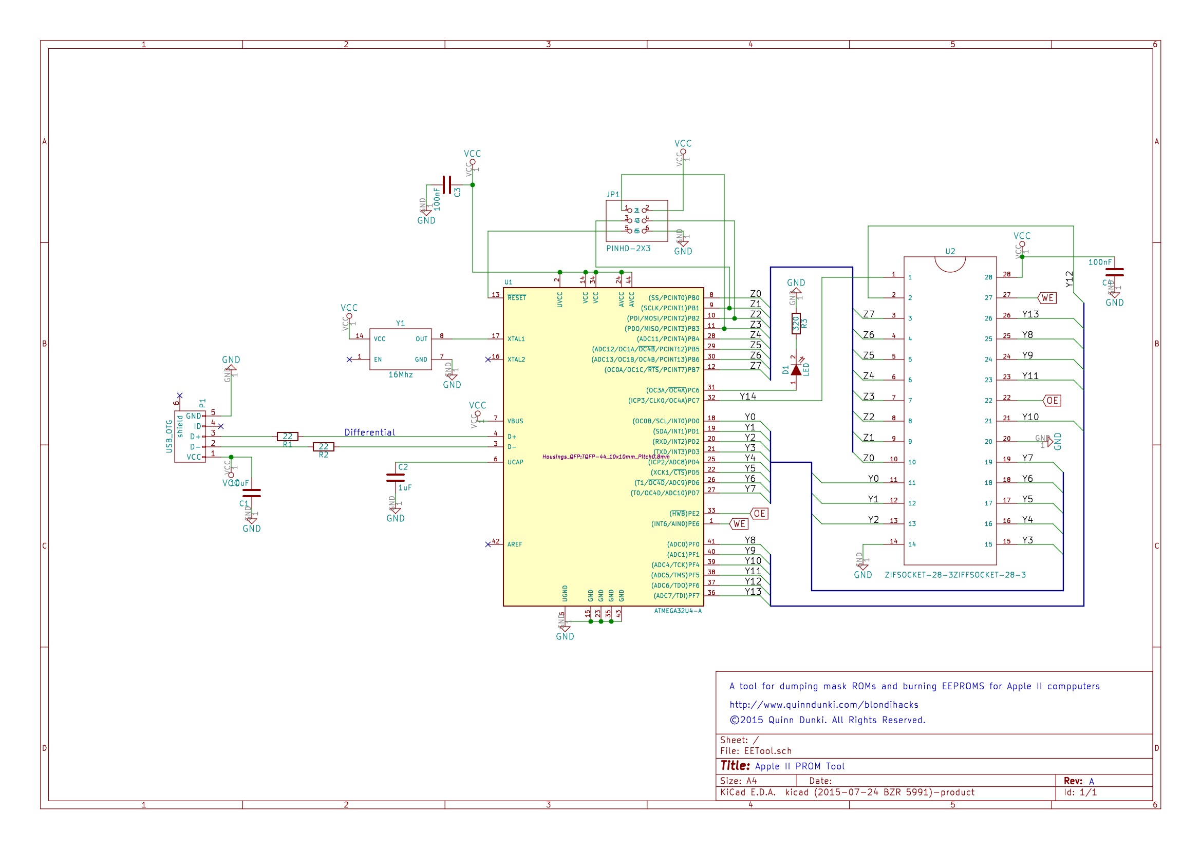
Here’s the schematic for the ROM tool. It’s literally just connecting all the GPIO to a ZIF socket for the ROM, and various support passives needed by the chips and USB. There’s also the usual decoupling caps and such, because physics.
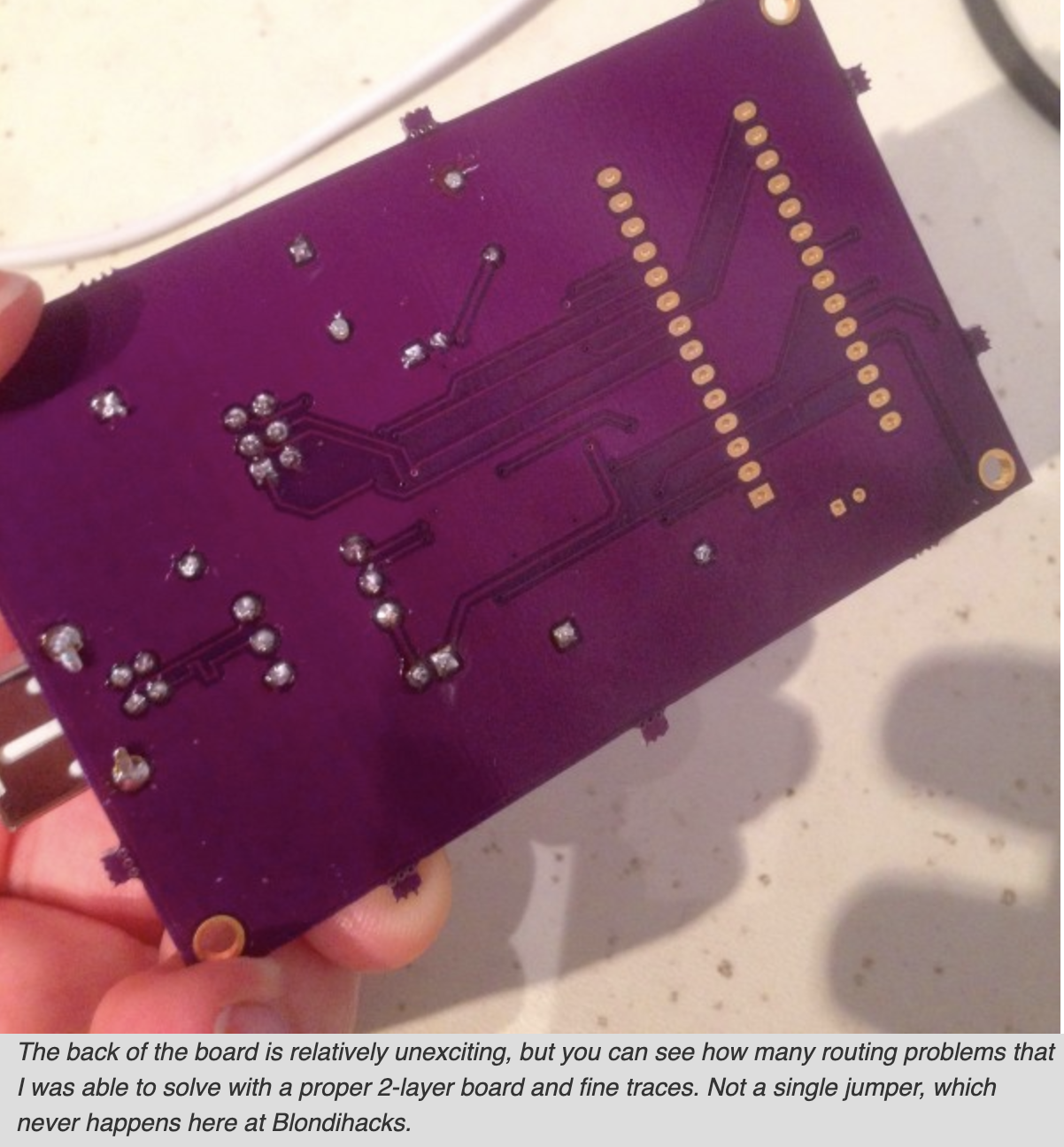
Next up is the PCB layout. I always enjoy this part of the process. It’s very satisfying. I knew there would be layout challenges here, because the microcontroller is a four-sided package, and the address lines on a 32kbit ROM are quite jumbled. A two-layer board would neatly solve all these problems, so I went for it.
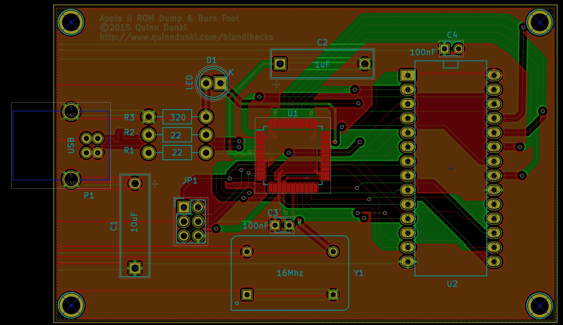
KiCad continues to impress. This was my first serious board layout since switching from Eagle, and I had very little difficulty producing a nice quality board.
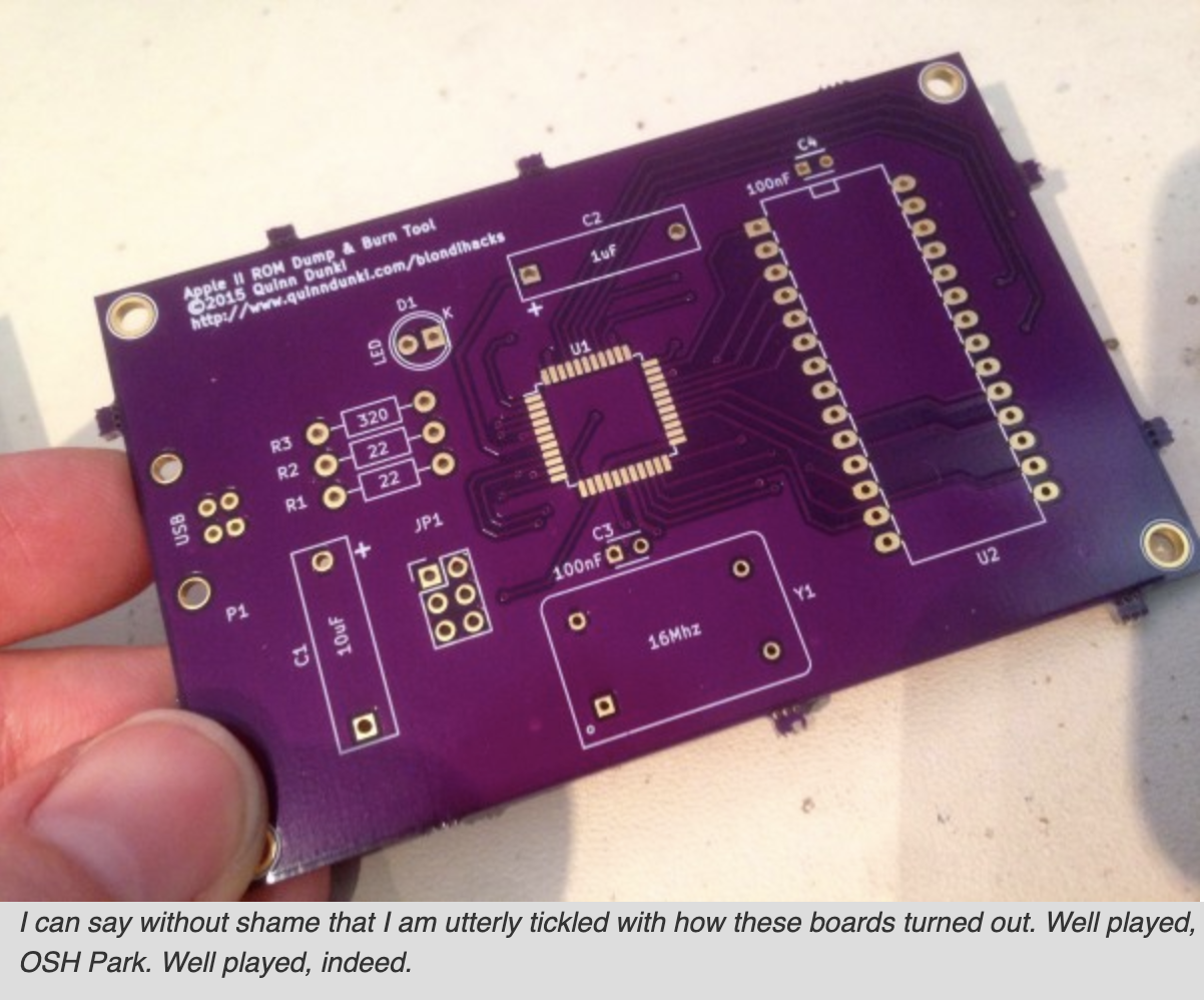
I decided to try one more new thing on this project. Since the very earliest days of Blondihacks, I’ve been a big proponent of etching circuit boards at home. It’s incredibly inexpensive, the turnaround is a matter of an hour or so, and the process is fun to do. However, there are some types of boards for which home etching is not a great solution. A good example of such a project is one involving 0.8mm pitch TQFP-44 surface-mount packages, multiple layers, lots of vias, and very fine traces packed closely together. Guess what? That’s what we need this time. Luckily, KiCad integrates very well with OSH Park, so I decided to give them a go. I chose them because they are well regarded, fairly inexpensive, relatively local, and their boards are purple. If I said that last part was not a factor, I would be lying. The boards they produce are BOOOOOOTIFUL.
The real downside to having boards made (aside from cost) is the time involved. Since they need to panelize your PCB with others to be able to make such small quantities for each person, it can take a while. In my case, it was about two weeks, which is actually better than I expected. These small-run board houses are also a good choice for SMT projects, because you want to keep your PCB size down (they charge by area), and they can do multiple layers with small traces. The other risk is that you’ll make a mistake on your board. You’ll want to be very careful with your layout before pushing that manufacturing button, because a mistake will cost quite a bit of time and money. If you have access to circuit simulators, that’s a great way to mitigate this risk. In my case, this design is so simple that the risk is low. It’s a good candidate to try out this process. As you’ll see, it was close to a raging success!
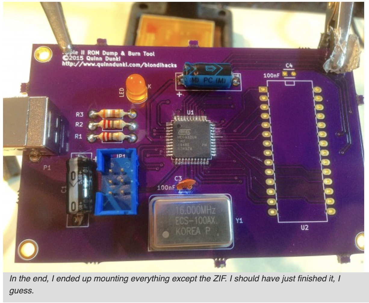
I described these boards as “almost” a raging success, because I did make one small rookie mistake. I trusted the footprint I had for the ZIF socket, and neglected to measure the actual parts I have here (which were acquired as surplus during a road trip to the TRW swap meet). The decoupling capacitor that I included for the ROM chip landed completely underneath the ZIF socket. It probably would be fine to leave the cap off (this is a small, low-speed board), but I simply mounted this cap on the back instead. The other thing I would change in this design is to make it a lot smaller. It could be made much more compact with better layout and component choices. I wasn’t thinking about the per-square-inch costs though, and I paid the price at manufacture-time.
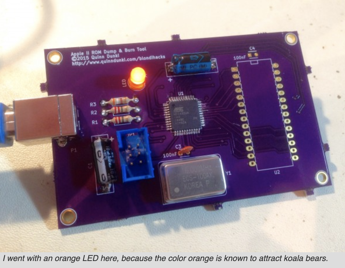
The next step was to mount sufficient components to get the microcontroller up and running. I don’t need to build the whole thing yet, because the bulk of this project will be software. I need just enough to talk to the ATMega. Some support passives are needed, the clock, the programming header, an LED for debugging, and the USB-related parts. Um… that turns out to be pretty much everything.
One other thing to note on this board…
With the hard bits out of the way, it’s time for the soft bits. Step one is to talk to the microcontroller over USB. This would be a thorny task, but luckily the amazing open-source project called LUFA has solved this problem for us. Really, I can’t say enough good things about this project, and the work Dean Camera has put into it. Go there now and donate to his project. Whether you want to make a keyboard, a game controller, a sensor device, a communications system, a mass-storage device, or something totally custom like this, LUFA has you covered. The samples he provides work great out of the box, although I do recommend reading the documentation. You want to make sure things are set up right for your application to avoid mysterious issues.
One other thing I recommend is, once you get LUFA up and running the way you need for the project at hand, strip it down as much as you can. Remove all unused portions of the source code and build pipeline. Otherwise your iteration times to download code to the microcontroller can get quite long. LUFA is very powerful, but there’s also rather a lot of code in it.
Next, it’s time to set up some communication. I opted to do this with a virtual serial port over USB. This is simple to write, gives me maximum flexibility in my protocol, and will work with any host platform. I happen to be on OS X, but all the code here is platform agnostic.
On the microcontroller side, the setup is simple. We initialize LUFA, then enter a tight loop to watch for data on the virtual serial port. For testing, we echo back anything we receive.
// Pseudo-code. May not compile or work
for (;;)
{
	// Check for host data
	uint16_t byteCount = CDC_Device_BytesReceived(&EETool_CDC_Interface);
	byteCount = MIN(byteCount,BUFF_SIZE-1);

	if (byteCount>BUFF_SIZE)
	{
		FatalError();
	}

	if (byteCount>0)
	{
		// Read all data from host
		int i;
		for (i=0; i<byteCount; i++)
		{
			int16_t value = CDC_Device_ReceiveByte(&EETool_CDC_Interface);
			if (value>=0)
			{
				gCommBuffer[i] = (uint8_t)value;
			}
		}

		// Echo it back
		CDC_Device_SendData(&EETool_CDC_Interface, gCommBuffer, byteCount);
	}

	CDC_Device_USBTask(&EETool_CDC_Interface);
	USB_USBTask();
}
eetoolTest3.c hosted with by GitHub
Once you have the LUFA USB client code running on the microcontroller, you should see the device when it’s plugged in. On unixlikes, you’ll see a /dev/tty device appear with a name like “tty.usbmodemXXXX”. On Windows, well, I dunno- stuff happens, I guess. Probably a cartoon paperclip is involved, and a lot of installing stuff and rebooting.
From here, I was able to run some test code on the microcontroller that would let me know the host is being seen and the USB is functioning normally. This was all done via the perennial debugging LED.
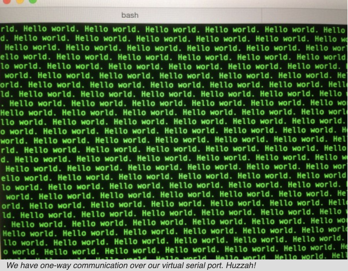
A useful tool for testing at this point is a golden-oldie unix tool called screen. It’s technically a VT-100 based virtual terminal environment manager, but it does a very nice job of listening to a serial port and telling us what’s happening on it. For example, configuring the microcontroller to spam text over serial, then opening ‘screen’ on that TTY device gives us this:
Now we need data going the other way. On the computer side, I figured a simple command-line tool to talk to this thing would be the way to go, so I dusted off my verrrry rusty Python skills. Here again I’m using an excellent open source library. pySerial is a platform-agnostic Python library that does a beautiful job of handling the heavy lifting of serial communications for you. On Mac and Linux, it interacts with TTY devices. On Windows, it interacts with COM ports. The documentation is also solid, and all the examples Just Worked™.
I set up the microcontroller side to respond to some basic command codes.
#include <avr/io.h>
#include <avr/wdt.h>
#include <avr/power.h>
#include <avr/interrupt.h>
#include <string.h>
#include <stdio.h>
#include <LUFA/Drivers/USB/USB.h>
#include "Descriptors.h"
#include "Macros.h"


#define BUFF_SIZE 512
#define LEDPIN 6
#define PREFIXBYTE 0x42
#define ROMSIZE 32768

void SetupHardware(void);
void FatalError(void);
void ClearCommand(void);
void Echo(const char* string);
void WriteBlock(void);
void ReadBlock(uint16_t startAddr, uint16_t length, bool maskROM);
void SetAddressMSB(uint8_t addr, bool maskROM);


void EVENT_USB_Device_Connect(void);
void EVENT_USB_Device_Disconnect(void);
void EVENT_USB_Device_ConfigurationChanged(void);
void EVENT_USB_Device_ControlRequest(void);


// LUFA CDC Class driver interface configuration and state information.
USB_ClassInfo_CDC_Device_t EETool_CDC_Interface =
{
	.Config =
		{
			.ControlInterfaceNumber   = INTERFACE_ID_CDC_CCI,
			.DataINEndpoint           =
				{
					.Address          = CDC_TX_EPADDR,
					.Size             = CDC_TXRX_EPSIZE,
					.Banks            = 1,
				},
			.DataOUTEndpoint =
				{
					.Address          = CDC_RX_EPADDR,
					.Size             = CDC_TXRX_EPSIZE,
					.Banks            = 1,
				},
			.NotificationEndpoint =
				{
					.Address          = CDC_NOTIFICATION_EPADDR,
					.Size             = CDC_NOTIFICATION_EPSIZE,
					.Banks            = 1,
				},
		},
};


typedef enum
{
	CMD_NONE,
	CMD_PING,
	CMD_STARTRW,
	CMD_READBLOCK,
	CMD_WRITEBLOCK
} Command;


Command gCurrentCommand = CMD_NONE;
uint8_t gCommBuffer[BUFF_SIZE] = "";
uint16_t gCurrentAddress = 0;


int main(void)
{
	SetupHardware();
	GlobalInterruptEnable();

	for (;;)
	{
		// Check for host data
		uint16_t byteCount = CDC_Device_BytesReceived(&EETool_CDC_Interface);
		byteCount = MIN(byteCount,BUFF_SIZE-1);

		if (byteCount>BUFF_SIZE)
		{
			FatalError();
		}

		if (byteCount>0)
		{
			// Read all data from host
			int i;
			for (i=0; i<byteCount; i++)
			{
				int16_t value = CDC_Device_ReceiveByte(&EETool_CDC_Interface);
				if (value>=0)
				{
					gCommBuffer[i] = (uint8_t)value;
				}
			}

			// Check for new command
			if (gCurrentCommand==CMD_NONE && gCommBuffer[0]==PREFIXBYTE)
			{
				gCurrentCommand = gCommBuffer[1];

				// New command
				switch (gCurrentCommand)
				{
					case CMD_PING:
					{
						Echo("PONG");
						ClearCommand();
						break;
					}

					case CMD_STARTRW:
					{
						gCurrentAddress = 0;
						PULSEC(LEDPIN);
						break;
					}

					case CMD_READBLOCK:
					{
						ReadBlock(gCurrentAddress,BUFF_SIZE,false);
						gCurrentAddress += BUFF_SIZE;
						break;
					}

					default:
						FatalError();
						break;
				}

				ClearCommand();
			}
		}

		CDC_Device_USBTask(&EETool_CDC_Interface);
		USB_USBTask();
	}
}

void SetupHardware(void)
{
	// Disable watchdog if enabled by bootloader/fuses
	MCUSR &= ~(1 << WDRF);
	wdt_disable();

	// Disable clock division
	clock_prescale_set(clock_div_1);

	// Configure IO pins

	// Address bus, LSB
	DDRB = QDDRB(0) | QDDRB(1) | QDDRB(2) | QDDRB(3) | QDDRB(4) | QDDRB(5) | QDDRB(6) | QDDRB(7);

	// Address bus, MSB
	DDRF = QDDRF(0) | QDDRF(1) | QDDRF(4) | QDDRF(5) | QDDRF(6) | QDDRF(7);
	DDRC = QDDRC(6) | QDDRC(7);		// Also LED output

	// Control bits
	DDRE = QDDRE(2) | QDDRE(6);	// Output enable  ,   Write Enable / Mask ROM high bit

	// Initialize control signals
	SETE_HI(6);
	SETE_HI(2);
	SETC_LO(LEDPIN);

	USB_Init();
}


void FatalError(void)
{
	for (;;)
	{
		SETC_LO(LEDPIN);
		_delay_ms(50);
		SETC_HI(LEDPIN);
		_delay_ms(50);
	}
}


void ClearCommand(void)
{
	gCommBuffer[0] = 0;
	gCurrentCommand = CMD_NONE;
}


void Echo(const char* string)
{
	PULSEC(LEDPIN);

	CDC_Device_SendString(&EETool_CDC_Interface, string);
}

void SetAddressMSB(uint8_t addr, bool maskROM)
{
	// Drives the high address lines to the specified value. These lines
	// are all mixed up to get around the holes in the AVR's IO space
	if (addr & 0x1)
	{
		SETF_HI(0);
	}
	else
	{
		SETF_LO(0);
	}
	addr>>=1;

	if (addr & 0x1)
	{
		SETF_HI(1);
	}
	else
	{
		SETF_LO(1);
	}
	addr>>=1;

	if (addr & 0x1)
	{
		SETF_HI(4);
	}
	else
	{
		SETF_LO(4);
	}
	addr>>=1;

	if (addr & 0x1)
	{
		SETF_HI(5);
	}
	else
	{
		SETF_LO(5);
	}
	addr>>=1;

	if (addr & 0x1)
	{
		SETF_HI(6);
	}
	else
	{
		SETF_LO(6);
	}
	addr>>=1;

	if (addr & 0x1)
	{
		SETF_HI(7);
	}
	else
	{
		SETF_LO(7);
	}
	addr>>=1;

	if (maskROM)
	{
		SETC_HI(7);		// For Mask ROM, this provides extra Vcc

		if (addr & 0x1)
		{
			SETE_HI(6);
		}
		else
		{
			SETE_LO(6);
		}
	}
	else
	{
		if (addr & 0x1)
		{
			SETC_HI(7);
		}
		else
		{
			SETC_LO(7);
		}
	}
}


void ReadBlock(uint16_t startAddr, uint16_t length, bool maskROM)
{
	if (startAddr >= ROMSIZE)
	{
		FatalError();
	}

	_delay_ms(10);		// Give the host a moment to set up before we flood them with data

	DDRD = 0;			// Data bus for input
	SETE_HI(2);			// Initialize Output Enable

	if (!maskROM)
	{
		SETE_HI(6);		// Write Enable to disable
	}

	for (uint16_t i=startAddr; i<startAddr+length; i++)
	{
		// Drive address lines
		PORTB = (uint8_t)(i & 0xff);	// LSB
		SetAddressMSB((uint8_t)(i>>8),maskROM);

		// Show falling edge to Output Enable
		SETE_LO(2);

		_delay_us(1);

		// Read the data byte
		uint8_t data = PIND;

		SETE_HI(2);
		uint16_t index = i-startAddr;
		if (index>=BUFF_SIZE)
		{
			FatalError();
		}

		gCommBuffer[index] = data;
	}

	// Send data to host
	CDC_Device_SendData(&EETool_CDC_Interface, gCommBuffer, length);
	_delay_ms(10);

	PULSEC(LEDPIN);
}


void WriteBlock()
{
	// Data bus for output
	DDRD = QDDRD(0) | QDDRD(1) | QDDRD(2) | QDDRD(3) | QDDRD(4) | QDDRD(5) | QDDRD(6) | QDDRD(7);

}


// USB Event Handlers
void EVENT_USB_Device_Connect(void)
{
	SETC_HI(LEDPIN);
}

void EVENT_USB_Device_Disconnect(void)
{
	SETC_LO(LEDPIN);
}

void EVENT_USB_Device_ConfigurationChanged(void)
{
	bool ConfigSuccess = true;

	ConfigSuccess &= CDC_Device_ConfigureEndpoints(&EETool_CDC_Interface);
}

void EVENT_USB_Device_ControlRequest(void)
{
	CDC_Device_ProcessControlRequest(&EETool_CDC_Interface);
}
eetool.c hosted with by GitHub
Next, I wrote the Python side of things.
#!/usr/bin/python

import sys, getopt, serial, binascii


class Mode:
	NONE = 0
	DUMP = 1
	BURN = 2
	CHECK = 3


class Command:
	PREFIX = 0x42
	NONE = 0
	PING = 1
	STARTRW = 2
	READBLOCK = 3
	WRITEBLOCK = 4

PONG = 'PONG'
BLOCKSIZE = 512

romfile = ''
serialport = ''


def main(argv):

	global romfile
	global serialport
	mode = Mode.NONE

	if len(argv)==0:
		usage()

	try:
		opts, args = getopt.getopt(argv,'dbcs:r:',['dump','burn','check','serial=','rom='])
	except getopt.GetoptError:
		usage()

	for opt, arg in opts:
		if opt == '-c':
			mode = Mode.CHECK
		elif opt == '-d':
			mode = Mode.DUMP
		elif opt == '-b':
			mode = Mode.BURN
		elif opt == '-s':
			serialport = arg
		elif opt == '-r':
			romfile = arg
		else:
			mode = Mode.NONE

	commands = {
		Mode.NONE:	usage,
		Mode.BURN:	burnROM,
		Mode.DUMP:	dumpROM,
		Mode.CHECK:	checkConnection
	}
	commands[mode]()

def checkConnection():
	if serialport=='':
		usage()

	print 'Checking connection to ' + serialport + '...'
	try:
		# Create the serial connection
		connection = serial.Serial(serialport,19200,timeout=1)
		print 'Found ' + serialport + '. Pinging EETool...'

	except (OSError,serial.SerialException):
		print 'Unable to find that serial port.'
		sys.exit(2)

	try:
		# Try sending a ping
		wrote = connection.write(bytearray([Command.PREFIX,Command.PING]))
		if wrote != 2:
			raise ValueError()
		print 'Sent', wrote, 'byte ping. Waiting for response...'

		# Did we get a pong back?
		while 1:
			numBytes = connection.inWaiting()
			if numBytes>0:
				break

		print 'Received', numBytes, 'byte pong'

		if numBytes != len(PONG):
			raise serial.SerialException
		response = connection.read(numBytes)
		if (response != PONG):
			raise serial.SerialException

	except (ValueError,OSError,serial.SerialException):
		print 'EETool is not responding. Check connections and try again.'
		connection.close()
		sys.exit(2)

	print 'EETool is online and ready for use.'
	connection.close()
	sys.exit(0)


def burnROM():
	usage()


def dumpROM():

	if romfile=='' or serialport=='':
		usage()

	print 'Connecting to ' + serialport + '...'
	try:
		# Create the serial connection
		connection = serial.Serial(serialport,19200,timeout=1)

	except (OSError,serial.SerialException):
		print 'Unable to find that serial port.'
		sys.exit(2)

	try:
		destFile = open (romfile, "wb")

	except OSError:
		print 'Unable to write to ROM file',romfile
		sys.exit(2)

	try:
		# Prepare to read
		wrote = connection.write(bytearray([Command.PREFIX,Command.STARTRW]))
		if wrote != 2:
			raise ValueError()

		print 'Requesting data from EETool...'

		totalSize = 0

		# Request all the blocks
		for blockNum in range(0,64):
			wrote = connection.write(bytearray([Command.PREFIX,Command.READBLOCK]))
			if wrote != 2:
				raise ValueError()

			while 1:
				numBytes = connection.inWaiting()
				if numBytes>=BLOCKSIZE:
					break

			if (numBytes!=BLOCKSIZE):
				print 'ERROR: Block',blockNum,'failed to download. Aborting.'
				sys.exit(2)

			response = connection.read(numBytes)

			# Write the block to our file
			destFile.write(bytes(response))

			sys.stdout.write('#')
			sys.stdout.flush()
			totalSize += numBytes

		destFile.close()
		print '\nDone! ROM is',totalSize,'bytes.'
		sys.exit(0)

	except (ValueError,OSError,serial.SerialException):

		connection.close()
		sys.exit(0)


def usage():
	print '''
Usage: EECommander -[d|b|c] -s <serial port> -r <rom file>
 -d: Dump the contents of the attached ROM or EEPROM to a file'
 -b: Burn the rom file to the attached EEPROM
 -c: Check your connection to EETool (no other action taken)
To find your serial port, connect EETool and try "ls /dev/tty.usbmodem*" on Mac or Linux.
On Windows, use a COM port name, such as "COM1". You can use the -c option to find out which one.
'''
	sys.exit(2)


if __name__ == "__main__":
	main(sys.argv[1:])
eecommander.py hosted with by GitHub
Note that this code is all a snapshot in time as of this writing. For the proper latest (and working) versions of everything, be sure and go to GitHub.
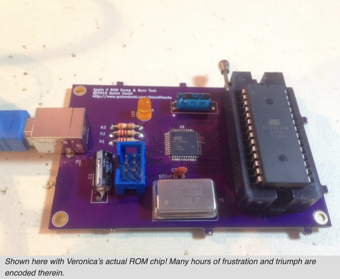
With that all hooked up, I fitted the ZIF socket, and got to work testing things.
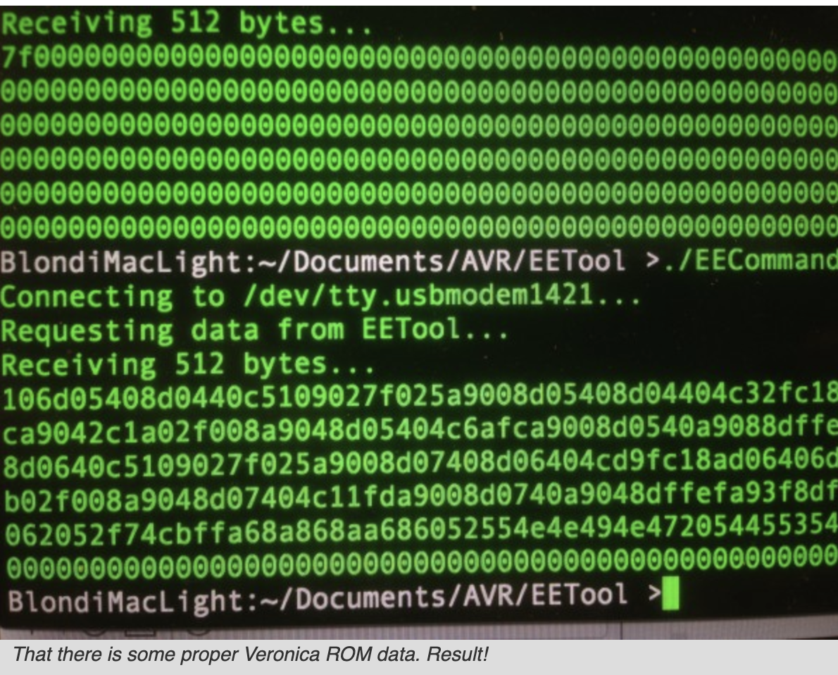
Now with ROM hooked up and the code all written, time to test for realsies! I connected everything, fired up the tool, and requested a dump of the ROM.
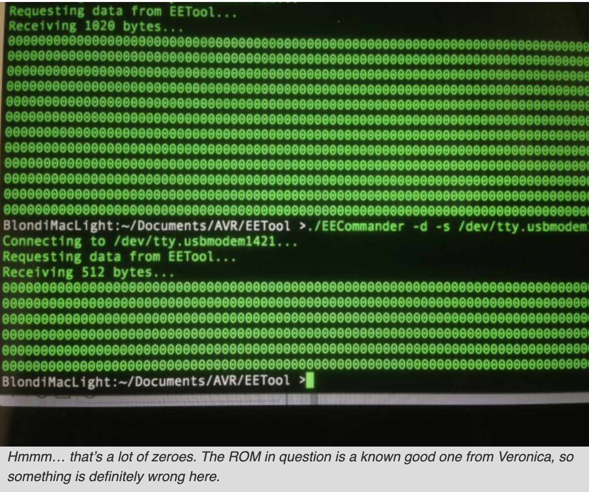
The next step in debugging anything is to eliminate variables. I know my serial communication is good from previous tests, so my interface to the ROM must be wrong. It could be either be problems with how the microcontroller is reading the ROM, or how it is packaging the data to send over serial. An easy way to isolate those cases is to hard-code a value on the data lines. Let’s have the microcontroller always report back a hard-coded value as though it had been read from the ROM.
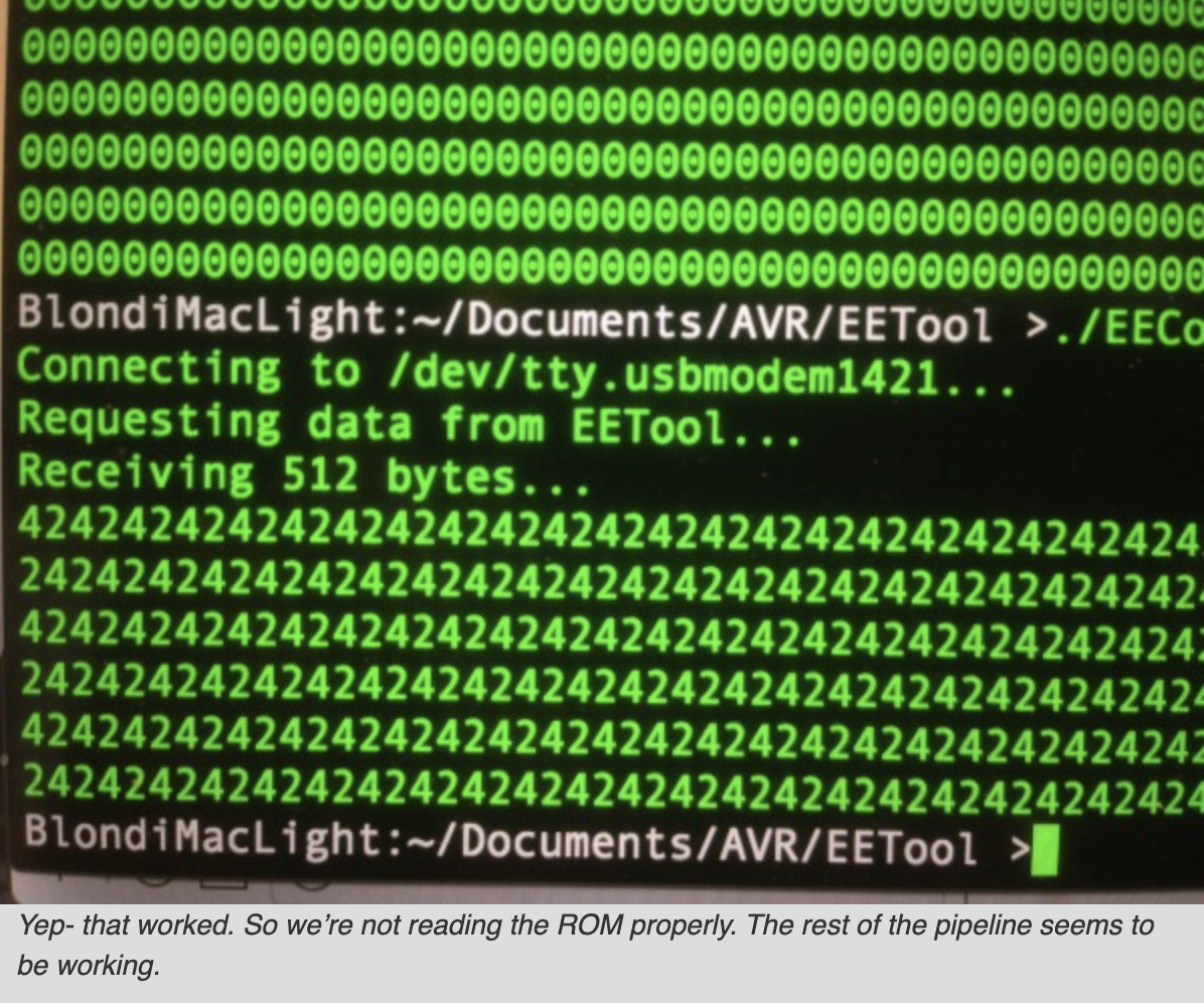
We now know the microcontroller thinks the data coming out of the ROM is all zeroes. This could be because address lines are not set right, data lines are not hooked up right, or possibly control signals are not behaving properly. How can we distinguish between all these possibilities? Time for the logic probe! Since we’re dealing with coarse data and low speeds here, we don’t need any fancy digital logic analyzer or anything. If the Chip Select is set right, and the address lines are counting up, then the data lines will be correct. The logic probe will tell us which of those conditions is not being met.
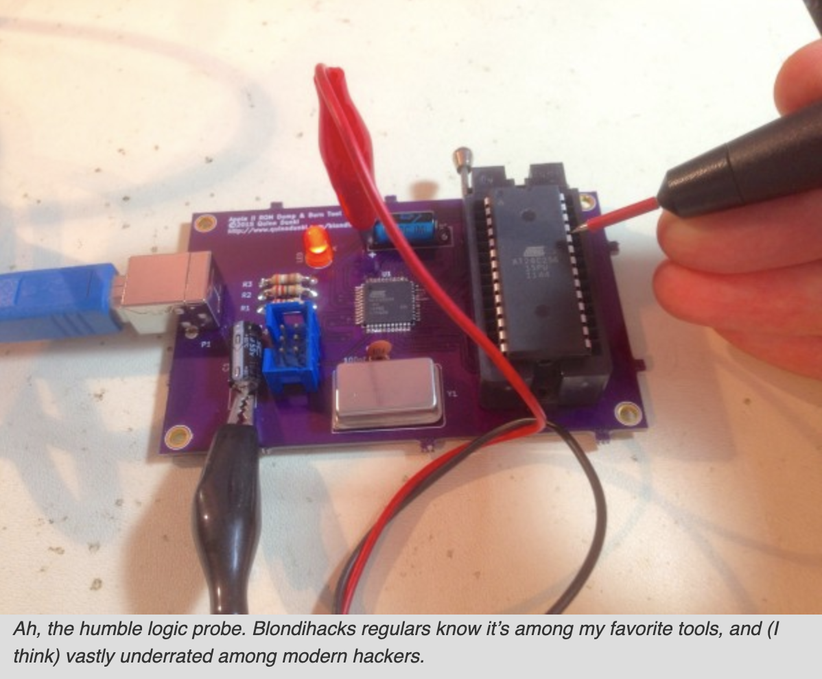
Some probing revealed the address lines were not all counting up properly. This is easily perceived (even at 16MHz) as a decreasing-pitch tone as you probe upwards on the address bus. A little debugging later (I hadn’t set some pin states correctly in my ATMega code), and we get some lovely sounds.
That’s 32kbits exiting one of our data lines at 16MHz. Music to my ears!
With that working, let’s get back to testing a ROM that we know the contents of (so that we know if the system is working).
I did have to iron out a few timing issues. The virtual serial port is fast, but the microcontroller and Python script are much faster, so some artificial delays are needed at a couple of key spots. Without them, bytes will be missed, or phantom random ones would creep in. We can’t have that- we need precision for this operation!
All that was left to do is wrap this basic code in a structure that reads one 512 byte block at a time, and sends these blocks over the wire to the host. The host writes these blocks to a file, and in this way the entire 32kbit ROM is dumped. I chose 512 bytes for the block size because that was the largest that LUFA’s virtual serial implementation seemed comfortable with. Much bigger, and bytes started disappearing. I suspect there’s an internal 1k buffer somewhere in the system that is the ultimate limit on this. Of course, much bigger than that, and we’d start to run afoul of RAM limits on the ATMega32U4 as well.
We now have some tools to really start digging into the Apple IIc Plus’ ROM code. Stay tuned for what we find!